 |
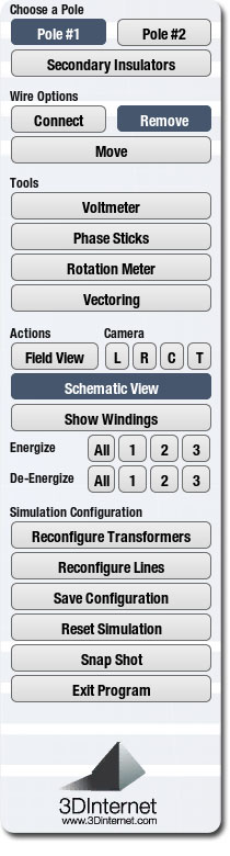
Choose a Pole: |
|
Allows you to toggle between Pole 1 and Pole 2 during configuration. Each bank on each pole can be configured independent from one another.
The Secondary Insulator button puts the user in the secondary connection page allowing for paralleling hookups. Pole 1 is on the left side and Pole 2 is on the right side. Here the phase relationship between both pole banks can be viewed prior to paralleling. A volt meter can be used here between each phase prior to paralleling the two banks. |
|
|
|
| Wire Options: |
|
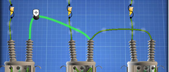
This part of the menu allows a user to connect wires, remove wires, or move (adjust) wires. When connecting wires, put your mouse over the desired point until a highlighted green color appears and click once. Then move your mouse to the location you wish to connect the wire. It will also turn green and then you can click your mouse once. This will connect the wire. Repeat this for each wire you wish to connect.
When removing a wire, click this button. You will see 2 small white bubbles appear on each wire. If you put your mouse on one of these bubbles, a garbage can will appear. Click once at this location to remove the wire.
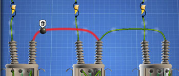
When adjusting the wire, click this button. Each wire will have two bubbles appear on them. Click and hold your mouse button down over this area and a small ball will appear. You can now drag the wire to the desired location. |
|
|
|
| Tools: |
|
| We have represented 3 types of tools. |
| 1. |
Voltmeter – used to measure AC voltage on the secondary side. This is a low voltage tool. If you attach this meter to the primary high voltage side, a warning will appear telling you this is not permitted and can cause harm. Hookup the leads of the meter to the desired spot in order to measure the voltage. Click once on a lead and now you can move it onto a wire or a bushing. When your mouse goes over the desired wire or bushing, the wire or bushing will highlight in a green glow and now you are ready to attach the lead by clicking once. |
| 2. |
Phase Stick – used to measure AC voltage on the primary side. This is designed for High Voltage and is measured in KV. The sticks attach the same way the voltmeter leads attach. |
| 3. |
Rotation Meter – used to measure clockwise or counterclockwise rotation of electricity. The leads attach on the secondary side of the transformer. |
|
|
|
|
| Camera: |
|
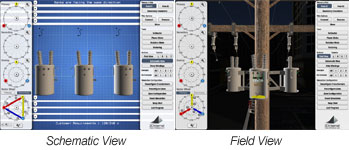
This allows you to switch between schematic and field view. Schematic view represents the lineman reference manual. The field view is a 3D representation of a real life view. The field view has presets to help navigate in different directions. You can also navigate in field view by holding down the space bar on your computer and then moving your mouse to the desired location. You can zoom in and out by using the mouse wheel.
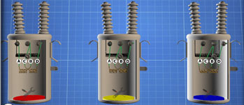
Also present under the camera heading is show windings and hide windings. This allows a user to view the winding. If the windings require changing or if the windings are in manual mode, you can attach new wires or move wires by clicking on the tools shown at the bottom of each transformer. When you show windings, you will see that each transformer is color coded for their number. This is handy when connecting transformers in field view as well as knowing which vector it represents.
Lastly under the camera heading are buttons for energizing cutouts or de-energizing cutouts. You can either choose to energize or de-energize all or individual cutouts. When cutouts are energized a yellow electricity bolt will be shown going through the cutout. At this time the vectors will energize as well.

|
|
|
|
| Simulation Configuration: |
|
| We have represented 3 types of tools.This final section of the menu allows a user to: |
| 1. |
Reconfigure Transformers – Allow a user to go back to the transformer configuration menu. |
| 2. |
Reconfigure Lines – Allow a user to go back to the line configuration menu. |
| 3. |
Save configuration – Allows a user to save wiring configurations to a location of a local or network drive. These configurations can be brought up again at the beginning of the simulator or they can be opened by other computers that have this program installed on them. |
| 4. |
Reset Simulation – This restarts the simulator back to the beginning taking out all wires and configurations. Only the primary line voltage and labels will remain. |
| 5. |
Snap Shot – Allows a user to take a screen shot of the wires in either schematic or field views. You are also able to take a screen shot of the configuration pages. These snap shots can be saved as PNG pictures anywhere on your local or network drive. Later they can be emailed or printed. |
| 6. |
End Program – Used to close down the simulator. |
|
|
|
|
|