|
|
Transformer 1 Configuration
In this part of the transformer configuration, you can custom design the type of transformer you wish to use in your configuration based on the following configurations:
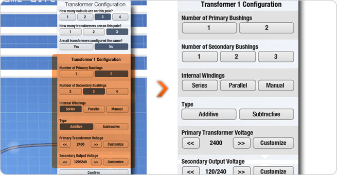
| Number of Primary Bushings: |
|
Select the number of primary bushings on your transformer.
|
|
|
|
| Number of Secondary Bushings: |
|
Select the number of secondary bushings on your transformer.
|
|
|
|
| Internal Windings: |
|
Select either Series or Parallel windings. This is used for matching up the correct transformer to the desired customer voltage.
If you choose Manual, all of the internal windings will be removed forcing you to wire the windings later in the simulator.
|
|
|
|
| Type: |
|
Select the polarity of the transformers.
|
|
|
|
| Primary Transformer Voltage: |
|
Select the transformer coil voltage on the primary. This is the same voltage that would be found on the label of the transformer.
|
|
|
|
| Secondary Output Voltage: |
|
Select the secondary output of the transformer. This would be the same voltage found on the label of the transformer.
|
|
|
|
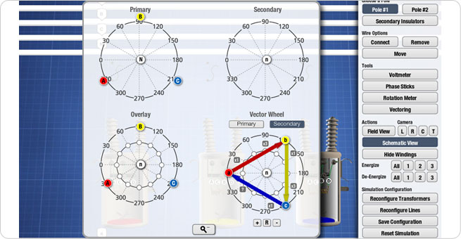
Here is a standard 3 transformer view in schematic view. The first transformer is on the left and is represented by a red vector. The inside of the transformer shows a red bottom. The middle transformer represents the second transformer and is represented by a yellow vector. The inside bottom of this transformer is yellow. The transformer on the right represents the third transformer and is represented by a blue vector. The inside bottom of this transformer is blue.

| 1 |
|
The primary wires are shown as the top wires above the transformers and have the capital letters A,B,C and N representing the phases. Above these wires are the words indicating if the banks face each other or if they are in the same direction.
|
|
| 2 |
|
Between the primary wires and the transformers are the cutouts. The cutouts are situated over H1 for each transformer.
|
|
| 3 |
|
The secondary wires are shown below the transformers and have lower case letters a, b, c and n representing the phases.
|
|
| 4 |
|
Below the secondary wires are words representing the Customer Requirements.
|
|
| 5 |
|
To the left of the transformer are the vector wheels.
|
 |
| |
|
| 1. |
The Primary Vector wheel represents the vectors for the primary. |
| 2. |
The Secondary Vector wheel represents the vectors for the secondary. |
| 3. |
The Overlay wheel is used to show the relationship between the primary and secondary vectors. |
| 4. |
The bottom vector wheel is used for labeling the primary and secondary vectors prior to wiring. This is used for labeling purposes only. This allows the user to visualize what is required before wiring the configuration. |
| At anytime you can expand the vectors by clicking on the expand button which shows a close up view of all of the vector wheels. |
|
|
|